Engines Tanks and Bulkheads Oh My!
Having described last time how we are able to generate the steam needed to both lift and power our globe circling airship, it is time to attempt a layout of the system so that we can see how it would fit into the hull. Since in my position as Flight Engineer I will be spending most of my role play time here I admit that it is a subject close to my heart
What would such an airship look like if it must include such a novel power and lift source?
I would like to say she would look like this...
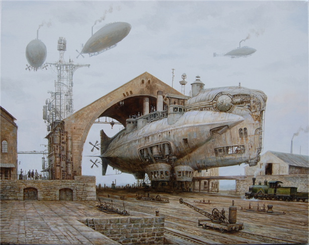 |
| Thunderer by *Voitv |
Unlike a vessel that floats on water, an airship is way more delicate in her balance and weight restrictions. The system I described last time is relatively heavy! My back of envelope calculations suggest that it would be the equivalent of all the engines, fuel and ballast water that the Hindenburg carried and then some. This weight is concentrated into a small area which has implications for where it is positioned in the hull.
The main propulsion engine in the stern with its large counter rotating props, powered by Tesla's wireless electrical system, is also fairly weighty for its power output. One other design idea I had was to use a larger number of smaller engines spread around the hull to avoid this concentration of weight, but it doesn't look quite so cool. (The "Splendid" requirement remember.) In this system these two weights, the power plant and main propulsion system, are at least small in area which simplifies the gross layout somewhat. By placing the power plant appropriately in the design we can balance the ship. The crew accommodations, cargo holds, and bridge are relatively light by comparison.
One other significant weight that needs to be accounted for is the steam condenser. This condenser is needed to recover the water from the high pressure steam used for power, plus the steam vented from the lift system when trimming the ship and any excess steam generated when the core is operating. Remember that our power core is either on or off, and when on must be cooled by steam generation constantly.
When I was originally doodling around with my design I had thought to give our airship a hull that was a shell of a light metal, like duraluminum, rather than the truss and fabric type structure the traditional rigid airships used. The condenser in that design was simply the upper surface of the hull itself. Alas, a quick calculation showed that a hull the size of the Hindenburg would be way too heavy built that way. In fact even using a light metal such as duraluminum the condenser becomes a significant weight in its own right, the third largest weight after the power core and main propulsion engine in fact.
Interestingly, if our airship was buoyed aloft by hydrogen, instead of steam, such a hull would work, and wouldn't need the weight of a condenser. This has some implications for a modern airship design using composite materials like modern graphite fibres etc.
Since we want our airship to be mostly appropriate to Victorian times, and use steam as its lifting gas, our airship will have a more or less conventional hull structure of duraluminum trusses with a fabric cover for the majority of the hull. The three primary weight blocks of power, propulsion, and condenser are laid out in such a way that the airship is in balance. The simplest way to visualize her is something like the Hindenburg with a pair of counter rotating props at the stern aft of the fins, a pair of funnels just forward of amidships, and what looks like a shell of metal on her upper hull just aft of the funnels.
I think that is pretty "splendid" really so our Captain should be happy.
Now let's get into the engine room and get our hands greasy, what would it look like? How do you arrange all the bits that are the core systems that support our airship in flight? As mentioned above the power core and its water tank are the heaviest parts and so must be the lowest in the hull. Water is a good shield for radiation so the rest of the engine room can be close to the core without problems. From an aerodynamic standpoint we don't want to disrupt the hulls smooth contour more than necessary so as much as possible we should keep everything inside the hull along the keel structure.
Here is my proposed gross layout. I would draw a picture but "Dammit Jim, I'm a Flight Engineer not an artist!"

At the lowest point, close to amidships, is the core and its tank. There is really no pressure in the tank so it doesn't have to be cylindrical like a railway engine boiler. However, a cylinder does minimize the weight of the tank relative to its volume. A sphere would be the best of course, but would be harder to fit into the hull. Above the tank is the main low pressure distribution header. This header leads low pressure steam direct from the core to the lift bags inside the hull. Valves in the header control this distribution. A low pressure channel also connects the header with the condenser on the upper surface of the hull. This channel is controlled by a valve and is the primary means to regulate the flow of low pressure steam between the lift bags and/or dumping the excess to the condenser.
Alongside the main distribution header is the main condensate header. This header's main purpose is to connect to the condenser on the hull and direct the condensed steam back to the main tank. This header also collects steam condensed from within the lift bags, as well as from the condensation collected from the inside of the hull itself that results from lift bag leakage.
Forward of the main tank is the engine room proper. Integrated into the forward bulkhead of the main tank is the high pressure boiler. Inside is the steel coil, filled with high pressure mineral oil, that leads directly into the heart of the power core. (Note: I've changed this slightly see the next article for the reasons why) Water from the main tank is pumped into this boiler where it is flashed into steam. The production of steam is regulated by the pump rate, if the pumps stop so does the steam production. This is similar to the way a water tube steam boiler worked on the more advanced steam cars of the period.
The heart of the engine room is the main turbine that takes the high pressure steam from the boiler and converts the energy to electrical power, by the use of an attached Tesla high voltage AC generator. This turbine is a special light weight version of that employed in high speed torpedo boats. Exhaust steam from the turbine is directed to an exhaust header. This header is connected to the main condenser.
A valve also connects the exhaust header directly to the funnels. When activated all the exhaust steam goes directly to the atmosphere, via the funnels instead of the condenser. This is used for two purposes, in case of a problem with the condenser that produces an unacceptable back pressure on the exhaust, and for when the Captain orders "flank" or emergency speeds and the flow of steam from the turbine would overwhelm the ability of the condenser to handle it. Doing so would rapidly deplete the water in the main tank of course, as none of it would be recovered by the condenser. We are a military ship, as well as an exploratory one, so such speeds may sometimes be necessary. Of course we could only run the ship flat out like this for a limited amount of time before we would be forced to shutdown the core. (Hmmm... I foresee some interesting role play possibilities with that, "Sorry Captain I canna push her much longer or she's goin ta blow!")
Ranged along the walls of the engine room are the auxiliary systems needed to support the primary one. I imagine this to look pretty similar to the engine room of a high speed destroyer of the period. Lots of brass gauges, pipes, pumps, and sparking, glowing, electrical devices of a mysterious and dangerous look.
I'll try to describe these systems in more detail in my next article.
Forward of the engine room is the domestic cargo hold, which carries the baggage and supplies for the crew. Aft of the main tank is a larger general purpose cargo hold.
So that will be my domain on this ship. How large a crew would be needed to man the engine room? Not many really. If we used a three watch system similar to that used by commercial surface ships and the great rigid airships, a crew of 6, 3 in each watch, including myself would be sufficient for normal operation.
Please join me next time as I continue to flesh out the mechanical side of this airship.
Don't worry, I haven't forgotten the crew's comforts, that's coming soon as well.
Keep your sightglass full, your firebox trimmed and your water iced.
KJ
Click here for the next article in this series.
You can follow the full design thread by clicking on the tag "Flight Engineer".


~ 0 comments: ~
~ Post a Comment ~