Showing posts with label Flight Engineer. Show all posts

Airship Construction

Friday, February 19, 2021 0 comments

Building the last great airship.

It is in 1930's propaganda style German, but there are some great images and film of construction details.
 
Released a year after the Hindenburg disaster, this film documents the construction process of the next zeppelin, the LZ 130. At this stage seen in the film, she was to have been nearly identical to the LZ 129 (Hindenburg), with only a small number of minor improvements (notably, her tail fins were 60 centimeters shorter in addition to some slight changes elsewhere). Later redesigned with new passenger decks and tractor-type engine cars designed for helium, the LZ 130, named the Graf Zeppelin (II), would ultimately be the last zeppelin ever flown.
 
Enjoy
Keep your sightglass full, your firebox trimmed, and your water iced. 
KJ


Description of a downed airship 1917

Saturday, April 4, 2020 0 comments

Secrets of the L49

Found this fascinating description of the interior of the downed German airship L49.

Enjoy
Keep your sightglass full, your firebox trimmed and your water iced.
KJ

From the ‘Nottingham Evening Post,’ 1st November 1917.


In the early hours of 20th October 1917, disorientated, suffering from airsickness, with only two engines working and attacked by Nieuports of Escadrille N.152, Zeppelin L49 came down in France.

It was examined in great detail by the British and French and an account of an inspection by an American “air expert” was published on 1st November 1917.

SECRETS OF THE L49.

FINDINGS OF AN AMERICAN EXPERT.

FROZEN WATER BALLAST.

An air expert of the Chicago Daily News, who visited the wrecked Zeppelin at Bourbonne-les-Bains, has communicated the following account of his impressions to the Press Association’s correspondent.

“Having just visited Zeppelin L49, which fell five kilometres from here, I have been struck by a number of facts. In the tanks there was still a large amount of petrol. The alcoholised water used for fluid ballast was frozen in the reservoirs, and in the 19 balloons of goldbeaters’ skin there was a great lack of gas. The only conclusion to be drawn from these facts was that the Zeppelin’s descent was caused by want of gas, and the impossibility of dropping ballast owing to the freezing of the water.

“Two meteorological authorities have informed me that the Zeppelin’s commander was, in all probability, deceived by the heavy wind like a mistral, which was more violent at the higher than at the lower altitudes. The highest altitude shown by the instruments was 7,000 metres, and rising to this height no doubt resulted in loss of hydrogen, and caused the liquid ballast to freeze. After descending to a lower altitude the commander was unable to reduce his ballast but went on in the hope of reaching Germany. French fighting machines, however, forced him to land. Hoping to set his machine on fire, the commander fired his pistol at the Zeppelin until stopped by a French sentinel. Fortunately he did not succeed. His only remark was ‘As you please, but I thought I had the right to destroy my machine when I surrendered.’


“COMFORTLESS CONVEYANCE.

“I went all over the captured airship from the turret platform to the cars. In the wireless telegraphy compartment I found some dry biscuits marked ‘Hanover,’ but was afraid to taste them for fear of poison.

“After all I had heard of Zeppelin comfort, I was surprised not to find much. On the contrary, I should not care to pass a night in one, even for the pleasure of bombing Berlin. The means of communication in the interior of the envelope consisted of an aluminium bridge 4½ inches wide of very fragile construction made of small pieces of aluminium and thin wood, with wire here and there to assist the passenger in keeping his balance. The sides of the bridge were merely waterproofed cloth – nothing else between the passenger and the ground beneath, but all, perhaps, that was necessary. But, still, I confess to being somewhat surprised at the makeshift appearance of the construction and workmanship, of which any English or French workman would have been ashamed.

“One notable exception, however, was the wireless room and installation, which closely resembled that of a transatlantic line of the latest type. According to a French expert who was sent to examine the apparatus, it included several new features of some importance. He assured me that in spite of the operator’s attempt to destroy the machinery before abandoning the ship, it would be possible to reconstruct the apparatus completely,

“Forward of the wireless room, the roomy bridge on the control station was furnished with a fibre mat, and with thick glass wind-shields on all sides. On the right and in the centre were two wheels for the elevating and directing rudders respectively, like those on a small motor yacht. A chart table stood on the right. Square stools, with rounded corners, made of thin wood, were used here elsewhere. They were so lightly made that when a French officer stood on one in order to reach the envelope it collapsed.

“IN THE ENGINE-ROOM.

“Aft of the wireless room stands the engine-room, where the largest of the five motors actuates the direct drive propeller. This is reached by a ladder which leads to a narrow path, 500 or 600 feet long, within the envelope. On the engine-room floor there was a folded parachute, which looked as though the engineer wore it attached to his shoulders until the moment when the commander decided to surrender.


“From this main motor-room, where the engine is twice the power of the others, I walked inside the envelope along a frail, narrow path of little sticks mounted on aluminium to a point where two diverging paths led to the nacelles.


“On the way I passed a tube of balloon cloth, enclosing an extremely light aluminium ladder, with rungs as far apart as possible, and leading to this was a wooden ladder reminiscent of those used for toy dog performances, but probably much less strong. I climbed uncertainly some 40 rungs to the top of the envelope, where was a small gun platform for two men and machine guns. I noticed here that the top of the envelope was almost white, shading gradually into black towards the lowest part.

“The aft nacelles, one on each side, were reached by ladders about eight feet long leading down from the interior of the envelope. Each of these contain two motors driving a single propeller – two motors being employed so that only one may be used on each side if it is desired to economise fuel.

“Inside the envelope are 19 balloons of goldbeaters’ skin, with smaller balloons built into them for the purpose of taking any overflow of gas, or if required they can be inflated by means of valves which are controlled from the navigation bridge forward.

“The envelope also contains water tanks of canvas, with a capacity of two hundred litres each, evenly distributed. This water ballast can also be controlled from the bridge. There are besides 16 petrol tanks of very solid construction, so arranged that any motor can be fed from any one tank. The rest of the contents include some spare parts, hammocks for the crew, which were probably not much used this last journey, and the aluminium framework that gives the envelope its shape.”
 
Image: 'The Sphere,' 3rd November 1917.

Inflating An Airship

Sunday, March 24, 2019 0 comments

Fill 'er up!

This photo shows the partially inflated gas bags of the British R33.

 From FB user Rick Zitarosa: "Gas lines at Lakehurst could provide 100,000 cubic feet per hour at 1-inch of pressure. Weather was a factor on working conditions and while the wartime-size ships could be inflated in a day or two Harold Dick advises that the inflation of the LZ129 commenced in mid January and took over 2 weeks. A critical juncture in the birth/life of a ship because in addition to having the riggers moving about attending to snags/folds/possible tears it was also necessary to ensure even inflation of adjacent cells and the proper addition and movement of sandbags, ballast, etc as the ship became buoyant."

Of course our ship, the HMAS Velvet Brush is inflated with steam, so while it wouldn't be quite so dangerous it would have been very hot!

The picture was posted on the awesome FB group Airships, Dirigibles and Zeppelins
There is an amazing collection of photos and expertise in that group.
Highly recommended is you are looking for an almost daily hit of Airship Wonderfulness.

Thanks for reading.

Keep your sightglass full, your firebox trimmed, and your water iced.
KJ

Practical Airship Design Part 7

Saturday, December 23, 2017 0 comments

Splendid she must be!

"How time flies when you are having fun."
Or conversely...
"Life is what happens when you have other plans."

This is the final post in my Practical Airship Design series, which I started way back in November of 2012, 5 years ago!

You can read that initial post and start the series here.

According to the "Contents and Prospectus" this post should have been:

"In conclusion, our Captain has ordered that she must, in addition to being one of the most technologically advanced airships of the age, be one of the most "Splendid"(tm) and this post will attempt to grant his wishes to the best of this poor flight engineer's ability."

Alas, I never got around to writing that post and cannot at the moment remember what I had intended to cover...

However, I think this series does need a formal conclusion, so if you have landed here please stay with me for a bit.

Like any good fictional tale, the action does not take place in isolation from the world around it.  Fictional tales always have a framework that supports the story. For speculative fiction like Steampunk, that framework/world may or may not bear much of a resemblance to the real one. The world of our Role Play group, "The Airship's Mess Deck", is no exception. The world in which we traveled, on the experimental airship the Velvet Brush which is the subject of this series, was similar to the real world physically but its technical and political history was slightly different.

As I mentioned in the first post we tried to limit the fantastical to keep the world realistic, with only a few key changes to make it interesting. Authors are allowed to create any kind of world they like in which to place their tales, but in the case of our Role Playing, we consciously decided to make our shared world a parallel one only slightly different. Physics still works like normal, and even the most fantastical elements are still "believable" in context.  The awesomely powerful core of the Velvet Brush herself being a good example.   

In our world the Velvet Brush was truly a technical marvel, the finest ship in the Royal Airship Navy. No other airship in the world could match her. Being experimental, and therefore fantastically expensive, she was never equaled or copied. During the course of our role play, she survived storms, sabotage, intrigues, and political machinations. Those of us who flew with her across the skies of the world always had her as a solid base for our adventures.

The crew and passengers have moved on to new adventures, however the shared world we created still exists in the imaginations of those who played in the Airship's Mess Deck (see more below). Like the crew of any "happy ship" in the real world, lasting friendships have resulted.

As the Engineering Officer, and eventually the Commander, of our ship, I see her in my minds eye still, an enormous silver and polished brass ship,  moving through the clouds, steam rising from her twin funnels, signal flags hanging from her rails. The Velvet Brush is truly as "Splendid" as she was intended to be. 

Thanks for following along as I tried to do some Practical Airship Design.

I hope you have enjoyed the journey.

Keep your sightglass full, your firebox trimmed, and your water iced.
KJ

==================================

Epilogue

My character's adventures, along with some of the crew, are posted as Serial Tales on this blog:
"Frozen Sky"
"Lost at Sea"
"Ice and Clockwork"

One of the passengers on our ship has her own adventures chronicled in the brilliant Maddie Hatter stories written by Jayne Barnard
Maddie Hatter and the Deadly Diamond
Maddie Hatter and the Gilded Gauge
Maddie Hatter and the Timely Taffeta
And more coming soon.

Oh, and Parasol Duelling is now a formal sport played all over the world!

Thanks for reading.
KJ

Titan Airship

Saturday, January 7, 2017 0 comments

Experimental airship like mine!

If you read my Practical Airship Design series the design might seem a bit familiar!

The airship described in this NASA paper uses hydrogen as a lift gas rather than steam but it is powered by a real equivalent of our core. Of course using hydrogen on Titan is really safe because there is no free oxygen anywhere to cause problems.


Fascinating.


"Radioisotope Stirling Engine Powered Airship for Atmospheric and Surface Exploration of Titan"

Author and Affiliation:   
Colozza, Anthony J.    (Vantage Partners, LLC, Brook Park, OH, United States);   
Cataldo, Robert L.    (NASA Glenn Research Center, Cleveland, OH United States)
   
Abstract:
    The feasibility of an advanced Stirling radioisotope generator (ASRG) powered airship for the near surface exploration of Titan was evaluated. The analysis did not consider the complete mission only the operation of the airship within the atmosphere of Titan. The baseline airship utilized two ASRG systems with a total of four general-purpose heat source (GPHS) blocks. Hydrogen gas was used to provide lift. The ASRG systems, airship electronics and controls and the science payload were contained in a payload enclosure. This enclosure was separated into two sections, one for the ASRG systems and the other for the electronics and payload. Each section operated at atmospheric pressure but at different temperatures. The propulsion system consisted of an electric motor driving a propeller. An analysis was set up to size the airship that could operate near the surface of Titan based on the available power from the ASRGs. The atmospheric conditions on Titan were modeled and used in the analysis. The analysis was an iterative process between sizing the airship to carry a specified payload and the power required to operate the electronics, payload and cooling system as well as provide power to the propulsion system to overcome the drag on the airship. A baseline configuration was determined that could meet the power requirements and operate near the Titan surface. From this baseline design additional trades were made to see how other factors affected the design such as the flight altitude and payload mass and volume.

Publication Date:     Jul 01, 2014

Keep your sightglass filled, your firebox trimmed, and your water iced.
KJ

Airship Rules

Sunday, March 6, 2016 0 comments

Basic Rules for Aerostatics

These Aerostatic Rules are taken from an Australian Government Document for getting ones "Airship Endorsement" on their pilot's license. Published in 2004 much of the document concerns the specific information an Airship pilot needs that the pilot of a heavier than air craft doesn't. One interesting point is that the rules are written for both hydrogen and helium airships! 

Enjoy

Keep your sightglass full, your firebox trimmed, and your water iced.
KJ


Recall the following basic rules for aerostatics and how to use them to calculate airship performance: 

  (a)  Rule 1
    Lift of an airship varies with the volume if all other conditions affecting lift remain constant.

  (b)  Rule 2
    Lift of a given volume of gas increases if barometric pressure increases and lift decreases if pressure  decreases.

  (c)  Rule 3
    Lift of a given volume of gas will decrease if atmospheric temperature increases and will increase if temperature decreases.

  (d)  Rule 4
    The higher the atmospheric humidity the less the lift.

  (e)  Rule 5
    There is no change in equilibrium due to a change in barometric pressure when the gas is free to expand.

  (f)  Rule 6
    Where air and gas temperature change an equal amount there is no change in equilibrium if the gas is free to expand.

  (g)  Rule 7
    An airship in equilibrium at any altitude will be in equilibrium at sea level, providing no weight is lost or gained and the superheat value is not changed in descending.

  (h)  Rule 8
    An airship rising from the ground in equilibrium will be in equilibrium at any altitude below pressure height if no weight is lost or gained and the superheat value does not change.

  (i)  Rule 9
    Barometric pressure will decrease approximately 1 inch Hg for every 1 000 feet of ascent in the lower atmosphere.

  (j)  Rule 10
    Atmospheric temperature will decrease approximately 2°C for every 1 000 feet ascent.

  (k)  Rule 11
    Gas volume is changed 1% for every 2.75°C change in gas temperature.

  (l)  Rule 12
    Gas density is changed 1% for every 2.75°C change in gas temperature.

  (m)  Rule 13
    1%  change in gas density or specific gravity for helium changes the lift 0.2% when at pressure height.

  (n)  Rule 14
    Lift is changed 1% for every 2.75°C change in superheat in flight as the gas is free to expand.

  (o)  Rule 15
    At pressure height (where gas is  not free to expand) the lift will change only 1% for 11°C superheat with helium and 1% for every 25°C superheat with hydrogen. This shows the danger in going from maximum daytime superheat conditions to zero superheat value at night if not properly understood and counteracted.

  (p)  Rule 16
        (i)  2.75°C superheat will lower the pressure height 360 feet at altitudes below 7 000 feet.
        (ii)  2.75°C superheat will lower the pressure height 400 feet at altitudes above 7 000 feet.

  (q)  Rule 17
    In ascending under average atmospheric conditions the volume will increase 1% for every 360 feet of  ascent in rising to 7 000 feet and increase 1% for every 400 feet above 7 000 feet.

  (r)  Rule 18
    In going above pressure height, lift is reduced 1% for every 360 feet below 7 000 feet and 1% for every 400 feet when above 7000 feet.

  (s)  Rule 19
    1% of the original mass of gas is lost if going 360 feet over pressure height when below 7 000 feet and 1% is lost for every 400 feet ascent above 7 000 feet altitude.

  (t)  Rule 20
    If, when full of gas, a weight equivalent to 1% of the lift is thrown over as ballast, equilibrium will be reached when 1% of the gas has been ‘valved’.

Airship Engineer's Slide Rule

Tuesday, March 1, 2016 0 comments

Slip Sticks for the Black gang!

Previously I posted about Nomography, i.e. the use of graphical tools for solving equations.

I have found a perfect example in the Internet Archives!
This article AN AIRSHIP SLIDE RULE By E. R. Weaver and S. F. Pickering, details the calculations and construction of a slide rule for working out problems concerning buoyancy, volumes, temperatures, lifting capability, and altitudes. Specifically for Airship crews this simple device is perfect for the analysis that any Flight Engineer would need to do as part of his duties.

The pamphlet contains the mathematical derivations for the scales and lots of sample problems that can be worked out using the slide rule.

Here is a picture of the slide rule:


And here is a page with some examples of the kinds of problems that could be worked out:


A very useful tool indeed.

Since this pamphlet includes the formulas for how the scales used on the slide rule are laid out, it should be possible to build one!

I think my Flight Engineer needs one, but adjusted for Steam as the lifting gas.

Keep your sightglass full, your firebox trimmed and your water iced.
KJ

Airship Feasibility Study from 1978

Friday, February 26, 2016 0 comments

Commissioned by the Province of Alberta!


This is a fascinating document that I found on the Internet Archives.
The Alberta Modern Airship Study was prepared for the Alberta Ministry of Transportation by the Goodyear Aerospace Corporation.

The study examines the realistic feasibility of using modern airships for transportation in Alberta. We had then, and still have today, large areas of the province that have narrow road access if they have access at all.

This study is packed with analyses, graphs, charts, and the technical feasibility of using airships.


Amazingly the study concluded that such use actually made sense!


Here is the conclusion (Spoiler Warning!)

STUDY CONCLUSIONS
The survey and ensuing economic case studies indicate that there are a large number of economically attractive applications for airships in the study area. It is apparent from the surveys and economic case studies that an airship operating company [rental service] is both necessary and economically viable.
The operation of airships within Canada is operationally a viable concept. Environmental factors, while severe in terms of cold, will not appreciably affect airship operations any differently than existing aircraft operating in Canada
.
The technology is available to successfully provide vehicles in the near term. Final definition of the vehicles can proceed immediately. Demonstration vehicles are needed to illustrate:
1) A lack of technical and operational risk to users
2) Economic viability
3) Regulatory agency compliance; and
4) To develop user awareness and confidence it is conservatively estimated that the following vehicle configurations and quantities could be supported by the study area :
Modern Conventional [Non-Rigid]       8 Vehicles
Modern Conventional [Rigid]               2 Vehicles
Heavy Lift                                            6 Vehicles

The earliest operational availability for the configurations considered during the study is:
Modern Conventional [Non-Rigid]       3 Years
Modern Conventional [Rigid]               8 Years
Heavy Lift Airship                                5 Years   

As in the case of the modern conventional non-rigid airships there appear to be two sizes of HLA vehicles having near-term applicability. An HLA with a useful load of 45,372 kg [50 tons] would find primary application in some remote construction activities, power line transmission tower erection, and the forest industry. The largest market in the study area for the HLA is probably in the 90,744 kg [100-ton] useful load range. The device would be used primarily in supporting large remote construction projects.
An excellent read and even though Goodyear obviously had a vested interest in selling Airships (they were the only ones making them in the 70s) they still covered all the bases.

Keep your sightglass full, your firebox trimmed and your water iced.
KJ

Practical Airship Design Analysis of a Real System!

Sunday, November 22, 2015 0 comments

Steam Plants for Aircraft analysed in 1926!

I found an interesting report from NACA (NASA's original name) concerning the analysis and experimentation of light weight steamplants for use in aircraft.

The paper is entitled "Steam Power Plants in Aircraft" and compiled by  E.E. Wilson at the Bureau of Aeronautics in 1926, and you can get the paper in PDF format here.

In this paper the author analyses a lightweight boiler setup capable of generating sufficient steam at high enough pressures to power an aircraft. He then estimates the weight and efficiency of a complete system model using this boiler and compares it to the current internal combustion power plants used in the heavier than air craft of the time.

The result of the analysis is that with the current state of the art in 1926, using steam power for heavier than air craft was NOT practical. This is not really a surprise given the power/weight ratio of even an efficient boiler and turbine setup. However there were two constraints that really tipped the analysis over against the use of steam power for aircraft.

  1. Fuel consumption/efficiency of steam power compared to internal combustion power plants.
  2. Weight and area of the system for condensing the steam for re-use.
If you have been reading the other parts of my Practical Airship Design series you will note that neither of those constraints exist in the design of our airship!

First the fuel consumption issue doesn't exist because of our fantastical core, which uses no fuel but produces steam at potentially very high temperatures and pressures. Second the condensation issue is moot because the exhaust steam can simply be added to the lift system and condensed on the hull condenser as described in Part 4.

Interestingly enough the author concludes something similar and even postulates a turbine electric propulsion system, which was very cool to read indeed!

Again we do not have any worries about efficiency in our design.


Fascinating to see this analysis and it is an interesting read if you are curious about the analysis of a real system that could be implemented in an airship like I have been describing.

Keep your sightglass full, your firebox trimmed and your water iced.
KJ

Here is the table of contents for the whole series of Practical Airship Design posts.

You can see all the posts related airships and airship design here.

Airship Technical Papers from the NACA

Friday, July 17, 2015 0 comments

An Airship Technical Gold Mine

Previously I reviewed one of the only books ever published on real airship design.
The author Charles P. Burgess worked for the National Advisory Committee for Aeronautics, the NACA.

During the heyday of the great rigid airships, in the first third of the 20th century, the NACA commissioned and collected a series of technical studies, papers and technological reviews of airship design. These papers show just how seriously rigid airships were taken as the future of heavy lift and long distance aircraft.

Recently NASA (the direct descendant of the NACA) has made scans of these reports and analyses available through the Internet Archive.

If you are curious check out this simple search:

Airship Technical Gold Mine 

Here you will find yellowed type written reports, with hand drawn graphs, diagrams, plans, and old photographs, documenting in detailed analyses the state of the art in Airship design in 20's and 30's.

The files are available in many formats including plain text, colour PDFs, html, epub and other ebook formats.

The titles alone make this old Flight Engineer drool!

Here are some examples to "wet yer whistle":

THE PRESENT STATUS OF AIRSHIP CONSTRUCTION, ESPECIALLY OF AIRSHIP FRAMING CONSTRUCTION
By Hans Ebner
1938


FULL-SCALE TURNING CHARACTERISTICS OF THE U.S.S. LOS ANGELES
By F. L. THOMPSON

CONTRIBUTION TO THE TECHNIQUE OF LANDING LARGE AIRSHIPS
By 0. Krell
PART I
Part II is here
From Zei'tschrift f'.r FLigteohnik und. Motorluftschiffahrt
September 28, 1928

RECENT RESEARCHES IN AIRSHIP CONSTRUCTION I
Forces of Flow on a Moving Airship and the Effect of he Control Surfaces
By H. Naatz
1928

Many of these reports are translations of German reports. The Germans were the acknowledged world leaders in Airship design at the time. The first report listed includes a German paper written in 1933 while the Hindenburg was under construction and before the loss of the Akron, which is noted in a footnote. The full report was not translated and acquired by the NACA till 1938.

Since these reports were typewritten they often contain typos, to me these little errors bring these fairly dry technical reports alive. In a way they show them as being human made. Prepared to record important information not just display elegant formatting.

For anyone interested in the technical details of real airship designs these reports are truly a gold mine of information.

Keep your sightglass full, your firebox trimmed and your water iced.
KJ

Here are some sample pages of the kinds of details included in these reports:


Airship Technology Speech

Tuesday, January 27, 2015 0 comments

A presentation!

My character in our role playing game was ordered to make a public presentation about some of the technological advancements embodied in our Airship. Basically the Government wanted to share these advancements with the Civilian companies as a way to boost the Empire's commercial competitiveness.

Just for fun I decided to actually give the presentation as part of an ongoing series of Absinthe Cafes here in Calgary.

I presented it in character and in costume, and it was a lot of fun.

Lt Cmdr(E) Maxwell MacDonald-Smythe
Photo by Lewis King
The information presented here is based on my Practical Airship Design series.

Here is the text of my speech.
Enjoy

Keep your sightglass full, your firebox trimmed and your water iced.
KJ
 --------
A January evening in the latter years of the 19th century.

Madame and Mr Chairman, My Lord, Ladies and Gentlemen.
Good evening.

I have been asked, by the Experimental Airship Division of the Royal Navy, also known as the the EAD, to present some of the technical details of one of the marvels of our age!
 
It is the hope of Her Majesty's Government that by releasing this, hitherto classified, information to the British business and manufacturing community, that the further development of these exotic and ground breaking technologies will help to maintain our Empire's lead in global commercial and military affairs.

Many of you have probably seen or heard the reports concerning the latest experimental airship of Her Majesty's Navy. You may also have seen the speculation concerning many of the developments and mechanisms that she has on board.

I have the honour to have been, and continue to be, her Chief Engineer.

And, Ladies and Gentlemen, as much as I would like to confirm that she is powered by exotic Indian demons and lifted by some remarkable gaseous material never seen before, and even that she can fly in the vast reaches of space, I must assure you that everything we will discuss this evening is in fact the product of the investigations into Natural Philosophy conducted over many years by brilliant men and women just like yourselves.

Nothing of what I will be showing this evening is in the province of the Metaphysical realm.

Having, alas, thus ruined your excitement concerning the information I am about to present to you, I hope that you will find the real information just as intriguing.

And so, to begin…


Here is the object of our discussion this evening.


Her Majesty's Air Ship The Velvet Brush!

She is truly a marvelous vessel, the largest self mobile object ever built by human beings!
Her dimensions are enormous,
  • Her Length is 245 m or 800 ft, longer than the largest ocean liner.
  • The Diameter of her hull is 42 m or 137 ft
  • She contains a Gas Volume of 231,000 cubic meters or 8 million cubic ft
  • She weighs uninflated 150 tons
  • When in flight trim she can carry a cargo load of 28 tonnes
  • Her propulsion system can move her at a steady cruising speed of almost 120 km/hour or  65 knots, thus making her one of the fastest ships in the Airship Navy.
  • Her maximum speed is still classified as is her maximum altitude, however; I can say that she has maintained that 120km/h value at elevations in excess of 1800m or 6,000 ft above sea level on numerous occasions. Her operational pressure height is 1200m or 4,000 ft under normal load conditions.
  • Her maximum cruising range is currently unknown!
I will say that on her very first flight she flew non-stop from the Royal Navy Airdock in Esquimalt British Columbia across the breadth of British North America, and the North Atlantic, to Portsmouth a distance of some 9000 Km or 5500 miles. This trip was accomplished in the dead of winter no less.

Ladies and Gentleman the Velvet Brush is a truly amazing ship, and despite the controversies and scandals attending her construction, she will be a model for future large Aerial Vehicles.

So to the technological developments that allowed the Royal Navy to construct such a stupendous vessel.

There are three developments that I will discuss this evening.

The first is the intellectual development that permitted her to be designed,

The second concerns the key material used in her construction,

And the third is the novel form of her lift generating system.

Many of you I am sure are aware of the advances in mechanical computation that have attended the construction of the Lovelace-Babbage engines in use at Oxford and Cambridge. The Difference Engine, designed by Charles Babbage under contract to the Royal Navy to produce navigational tables, was completed in 1849. Babbage completed the design for his more advanced Analytical Engine but it had not been constructed by the time of his death in 1871.

However his associate Augusta Ada King, Countess of Lovelace, continued working on the design, again under contract to the Royal Navy and the new machine was produced and first began calculations in 1880. Along with the physical design of the machine, the countess was instrumental in composing the grammar for the lists of instructions that the machine uses. Her treatise on "Simulation of mechanical processes by computation", published when she was in her 60s in 1875, earned her a worthy place in the Royal Academy.

One of the first applications of the Lovelace-Babbage machine was the analysis of stress and strength in the metal components of ships hulls. It was also used in the computations to design the first Naval scouting Airships and the first Cunnard Passenger Airships that followed soon thereafter.

The design of such a magnificent vessel as the Velvet Brush would not be possible without the speed of computation, and the elegance of the Countess's Analytical Engine Grammar.

As part of the technology transfer program of her Majesty's Government, two new Lovelace Babbage machines, of the latest design, will be available for public use starting later in the year. One will be in London the other in Liverpool.

Now, as to the construction of the Velvet Brush herself.

Practical Airship Design Part 6a

Sunday, January 4, 2015 0 comments

More Domestic Tranquility Systems


In Part 6 I described some of the crew spaces and layout of our airship.
This post is a document I produced for our RP group, to give the other players a mental map of the spaces in which we conduct our role play. It references some of the adventures we have had too.

Keep your sightglass full, your firebox trimmed and your water iced.
KJ

The table of contents for the whole Practical Airship Design series is HERE.

You can find all my Airship posts by clicking on the tag "Flight Engineer".

Interior layout HMAS Velvet Brush


Since some of our adventures are centered around the physical aspects of our fine ship, I thought it might be useful to have a mental map of how the ship is laid out.

I'm a lousy graphics guy so my attempt at doing a diagram was a miserable failure. Although I could draw one on paper. I might do that and scan it to include here if this description isn't good enough.

Probably the biggest thing to keep in mind is that even though our ship is enormous all the interesting stuff is along the bottom of the hull. If we exclude the lifting part we are a long narrow set of spaces connected by the keelwalk.

What I find fascinating is how the design of our ship has evolved over the last year. There have been some interesting changes that have resulted simply from the need to have identified places in which episodes of our story could take place. A good example is the position of the Captain's cabin. Originally we didn't have one, because we didn't really have a Captain smile Once Captain Hodgson arrived we needed a place for him to hang out.  Another example is the "viewing platform" that Madame flew her bird off of while flying from Esquimalt.  We were never specific about where that was on the ship, it had to be close to her cabin though because she could get there easily. Having it used by the British Consul in Venice means it must be fairly large and accessible from the accommodations.

At the risk of being arbitrary then, the following is the layout as it seems to be at the moment. We can change some parts if needed as long as they don't get in the way of what we already have. We can also do a refit at an Air Dock sometime too, to add extra spaces if needed.
 When thinking about the cabins remember that this is essentially the first floor of a two story block. So far (as of May 20) the upper floor is not populated with named spaces, with the exception of the Captain's cabin right at the front above the Flight-deck and possibly the cabin that First Officer MacLeod was in when the KAR* exploded in Portsmouth.

The Keelwalk is a triangular passageway integral with the base of the ship's hull, inside the circular cross section. This walkway runs the entire length of the ship, some 700 feet, from the Captain's Cabin in the bow all the way to the lower fin at the stern. Note that this walkway is above the cabins in the diagram. It is reached by a ladder outside the Bubble Bath Room aka "Secured Storage" as well as a ladder in the Flight-deck that goes directly into the Captain's Cabin.

Personally I view this passageway as being a corridor like the one that runs through the accommodations with a couple of (as yet undefined) cabins on either side.  Once you head aft of the accommodations however, the keelwalk becomes a simple triangular girder framed walkway, like that in the Hindenburg.

Just aft of the accommodations there is a ladder that runs all the way up to the top of the hull. This ladder reaches an observation platform in font of the bases of the funnels.  Climbing this ladder is quite a process and very hot as it is between two of the lift bags which are filled with steam of course.

The "Last Step" is the main access to the ship and is on the Starboard (right) side just aft of the galley as you can see on the diagram.

Engineering is located nearly 300' aft of the accommodations! This is another space similar in shape to the accommodations and also below the hull. It is reached by a ladder down from the keelwalk.  I've described the layout of engineering on my blog if you are interested.  There are no windows in Engineering except perhaps one over Max's desk and one in the break room for the off watch. Above Engineering on either side of the keelwalk is all the steam and condensate piping. the Tesla power transmission system extends from Engineering right up to the center of the hull which is 50' above. The keelwalk is offset as it passes this device.

There are two cargo holds in our ship. Originally I had them attached to Engineering but not extending all the way to the forward accommodations, but that doesn't work given the ships behaviour, and the movement of loose bits of cargo, in the storm over the Baltic. Also the ease in which people seem to be able to get into and out of it means it needs to be closer to the main accommodations up forward.  Placing the forward cargo hold as an extension of the accommodations makes a lot of sense and also provides a perfect place to put the viewing platform.

This is my proposed layout of the forward hold. From the diagram of the accommodations you can see that the Bubble Bath room is right at the end of the central corridor. I propose that the cargo hold is immediately aft of that space and extending maybe another 60' or so. The forward part of that hold, right up against the aft wall of the bubble bath room, is now walled off with the "secret" machinery installed by the company workman sealed inside. Briggs' armoury and weapons storage is against the wall of the secret compartment.

Access to the cargo hold is just aft of the end of the accommodations and is by a hatch with a ladder down from the keelwalk which runs over the top of the hold.  There is an outside access to the cargo hold in the form of a large cargo door in the side of the hold. This is not normally opened while in flight of course. The hold has no windows or other accesses.

The "aft viewing platform" is a broad platform built around the outside of the forward cargo hold. It is reached from a doorway in the accommodations just outside the Bubble Bath Room. This platform has  a railing is the perfect place to observe fireworks and the passing world below.

The aft cargo hold is a similar extension of Engineering. It is reached by a ladder and hatch from the keelwalk. It also has a large outside cargo door that is sealed while in flight.

The general crew bunk in spaces above the forward hold on either side of the keelwalk and the Black Gang bunk in similar spaces over the aft cargo hold.

Things to keep in mind from an RP perspective is that it takes time to get from Engineering to the Flight-deck, especially for Max who has to use a cane. smile

With the exception of the Captain's Cabin, and the crew and Black Gang's bunks, everything is BELOW the keelwalk. That means having to climb a ladder to get to the keelwalk to move forward or aft in the ship.

I hope this will be of some help in keeping track of what's where in our fine ship.

Part 7 is here.

*KAR Kamikaze Automaton Rat. An automoton shaped like a large rat and loaded with explosives.

"The Night Mail" Rudyard Kipling 1905

Saturday, October 18, 2014 0 comments

A Rudyard Kipling SF tale.

Reading the Log of the H.M.A. R 34 I posted about last time I came across this gem:

10.15 a.m. Weather report from St. John's :"Barometer 1010.2.Steady ; temperature 44 F. Fog. Visibility about half a mile, fog seaward, wind westerly, very light."
This is all right.
Turned in for an hour, but unable to sleep.
Become absorbed in Kipling's story of "The Night Mail" in Actions and Reactions. Think I must have read this story fifty times! Every time I read it the more impressed I become with the reality of its prophecies, which give one that very same  "atmosphere" of Aerial Liner travel that we are actually experiencing during every
moment of this journey.

 A quick lookup on Google and I discover this wonderful tale:

With the Night Mail

A STORY OF 2000 A.D.

(TOGETHER WITH EXTRACTS FROM THE CONTEMPORARY
MAGAZINE IN WHICH IT APPEARED)

BY
RUDYARD KIPLING

Illustrated in Color
BY FRANK X. LEYENDECKER
AND H. REUTERDAHL

NEW YORK
Doubleday, Page & Company
1909


This is a wonderful SF tale about traveling on a Mail Packet across the Atlantic. A delightful look at a future where airships are as much a part of regular air traffic as are heavier than air craft.

You can read the whole book, complete with the original colour illustrations, at Project Gutenberg here:

"With the Night Mail" by Rudyard Kipling

A bonus is the ads and articles that make up the "EXTRACTS FROM THE CONTEMPORARY
MAGAZINE IN WHICH IT APPEARED" portion.  Here is an example:


 High Level Flickers
"He that is down need fear no fall"

Fear not! You will fall lightly as down!

Hansen's air-kits are down in all respects. Tremendous reductions in prices previous to winter stocking. Pure para kit with cellulose seat and shoulder-pads, weighted to balance. Unequaled for all drop-work.  Our trebly resilient heavy kit is the ne plus ultra of comfort and safety.  Gas-buoyed, waterproof, hail-proof, non-conducting Flickers with pipe and nozzle fitting all types of generator. Graduated tap on left hip.
Hansen's Flickers Lead the Aerial Flight
197 Oxford Street
The new weighted Flicker with tweed or cheviot surface cannot be distinguished from the ordinary suit till inflated.
So what exactly is a "flicker" a parachute or some sort of personal lift device?
Lots more intriguing bits and pieces of the world of 2000 AD as envisioned by Rudyard Kipling.

Keep your sightglass full, your firebox trimmed and your water iced.
KJ

The Log of H.M.A R34

Tuesday, October 14, 2014 0 comments

Trans Atlantic Airship!

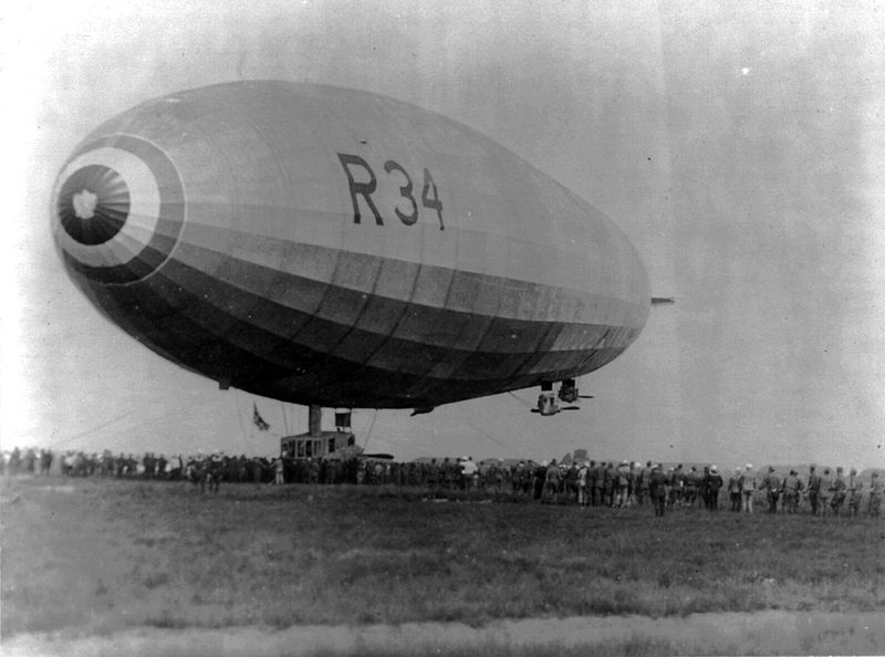
The  R 34 was built in 1918 for the Royal Navy by the William Beardmore and Company in Inchinnan, Renfrewshire, Scotland. Her design was influenced strongly by that of a German Zeppelin that had been captured almost intact in England during the war.

In 1921 it was decided to attempt the first ever return East to West flight across the Atlantic.

From Wikipedia

It was then decided to attempt the first return Atlantic crossing, under the command of Major George Scott.[11] R34 had never been intended as a passenger carrier and extra accommodation was arranged by slinging hammocks in the keel walkway. Hot food was prepared using a plate welded to an engine exhaust pipe.

The crew included Brigadier-General Edward Maitland and Zachary Lansdowne as the representative of the US Navy.[12] William Ballantyne, one of the crew members scheduled to stay behind to save weight, stowed away with the crew's mascot, a small tabby kitten called "Whoopsie"; they emerged at 2.00 p.m. on the first day, too late to be dropped off.[13]

R34 left Britain on 2 July 1919 and arrived at Mineola, Long Island, United States on 6 July after a flight of 108 hours with virtually no fuel left.[14] As the landing party had no experience of handling large rigid airships, Major E. M. Pritchard jumped by parachute and so became the first person to reach American soil by air from Europe. This was the first East-West crossing of the Atlantic and was achieved weeks after the first transatlantic aeroplane flight. The return journey to RNAS Pulham took place from 10 to 13 July and took 75 hours.


As an observer on board the crossing Air Commodore Maitland kept a log of everything that occurred and this was published as a book. Illustrated with 35 photographs taken during the flight, this is real airship adventure!


Here is the introduction to this fascinating read.
IT is often thought necessary to preface a 
first literary effort with apologies from the author 
for its shortcomings. In this instance no one 
could be more aware of such a necessity than 
myself. But am I entitled to make apologies? 
R 34 is not a literary effort neither, therefore, 
am I an author. 

In writing a story such as this, the obvious 
and comparatively simple course would have 
been the adoption of the conventional narrative 
form, helped by notes and memories, ample 
time and thought and a comfortable arm-chair. 

Apart, however, from its practical usefulness 
or official importance, R 34's journey was just 
one long, wonderful and delightful experience. 

To look upon this journey coldly as part of 
yesterday, or to treat it with recognized con- 
vention, would be to lose both the essence and 
the spirit. 

My only hope of convincing my reader of this 
is to try and induce him to share our adventure- 
taking him with us upon our flight. 

Every word of this diary was written on board 
the Airship during the journey, with the exception 
of the explanatory footnotes and, of course, the 
appendices : the writer perched in odd corners, 
and amid continuous interruptions and ever- 
changing surroundings, to the silent accom- 
paniment of the wireless, like ghostly whispers 
across lonely space. Every incident, important 
or trifling, was recorded at the actual time of 
happening. Even to stop to focus or to pigeon- 
hole these would have been to destroy actuality. 

If only I can share a little of that fascinating 
and buoyant adventure with any readers of these 
pages I shall be content, I only hope my ship- 
mates may not find their journey too dull; if 
they do they must not blame R 34, for the 
fault will be mine. 
You can read this wonderful adventure in its entirety at the Internet Archive


For those who want a hard cover version of this book a reprint  edition is also available from Amazon
 
Keep your sightglass full your firebox trimmed and your water iced.
KJ


Title
The Log of H.M.A. R34
Journey to America and Back.

Author
Air-Commodore E. M. Maitland
C.M.G., D.S.O, A.F.C, Royal Air Force

Date
1921

Pubisher
Hodder and Stoughton
Re-published
Kessinger Publishing (Sept. 10 2010)

ISBN
1164269127

Airshipwreck!

Saturday, March 8, 2014 0 comments

The age of the airship was short lived.

It lasted scarcely more than a a quarter of a century and during that time very few of these elegant and enormous machines survived very long. There are only a handful that survived the rigors of  flight to be broken up. Most were destroyed by fire, accident, storm or carelessness and yet as the author of this marvelous book, Len Deighton, says:

 For me the airship has a magic that the aeroplane cannot replace. The size is awesome, the shape Gothic; a pointed arch twirled into a tracery of Aluminum... the airship remains one of the greatest triumphs of structural engineering the world has ever seen.
This slim volume, written and compiled by Len Deighton and Arnold Schwartzman, is a chronicle of every airship disaster, accident, crash, and explosion. Although a chronicle of dismay it is in a sense also the chronicle of an experiment in engineering magnificence. Even in the grainy black and white images of the twisted and broken girders, torn envelopes, and flaming wreckage there is elegance. The immense labour of the design, the intricacy of the parts, and the bravery of those who would dare to take such vehicles into the skies, are apparent.
In this book, with the help of experts, I have told the story of the airship's failure. It shows the daunting task that the airship designer faced. Perhaps all simple acts of faith bear an imprint of absurdity, and you will find it here. But the book is intended as a tribute to the master builders and their aluminum marvels. This generation of engineers dared to build their cathedrals in the sky; no wonder then that so few of them stayed there.
--Len Deighton
Keep your sightglass full, your firebox trimmed and your water iced.
KJ

Title
Airshipwreck

Author
Len Deighton
Arnold Schwartzman

Publisher
Jonathan Cape Ltd
London

Date
1978

ISBN
0-224-01384-X

Airship Pilot No. 28

Sunday, September 22, 2013 0 comments

Memoirs of a real Airship Pilot!

I acquired this wonderful book a month ago at a "Antique Mall" in Airdrie Alberta.

Written by T.B. Williams and published in 1974. This book chronicles the his adventures after joined the Royal Navy in 1915 to become an Airship pilot. In the days before the fixed wing heavier than air craft became the standard military aircraft, the hydrogen filled airship, non-rigid and semi rigid were the mainstay of the Royal Navy for scouting and convoy protection from submarine attack near the coast of England. No convoy suffered a loss from submarine attack when one of these airships was in attendance during their approach.

Williams was awarded Airship Pilot Certificate no 28 in 1917. He was instrumental in the training of other pilots as well as being on the crew of the Italian semi-rigid that was the first aircraft to ever fly from Italy to England. He eventually was promoted to Captain.

A fascinating look at the uses that the Royal Navy, and later the Royal Airforce put these primitive but very useful craft too.

Captain Williams also chronicles the post war decline and attempted resurrection of the Airship, for commercial use including the R100 and R101.

The book is filled with interesting photographs and has an extensive bibliography of books that will be very useful to track down.

A must read for anyone interested in this unsung chapter of military aviation.

Keep your sightglass full, your firebox trimmed and your water ived.
KJ


Title
Airship Pilot No.28

Author
Captain T.B. Williams A.F.C.

Publisher
Willia Kimber and Co.
London

Date
1974

ISBN
07-183-0153-6

Our Airship!

Sunday, August 18, 2013 0 comments

Finally

I managed to get a reasonable diagram put together of the airship I have been designing and describing in my Practical Airship Design series.

The diagram is loosely based on the Graf Zeppelin. I was going to use the outline of the Hindenburg which is smoother but I like the look of the slightly more primitive shape of the Graf.

The base shape was done by Wolf  and can be found along with similar drawings of many airships real and proposed at http://wolfsshipyard.com/www.wolfsshipyard.mystarship.co/Misc/Airships/Airships.htm  
That page is definitely worth a visit if you are interested in Airships!

So here she is in all her glory the newly christened HMAS Velvet Brush.

HMAS Velvet Brush by Kevin Jepson based on the Graf Zeppelin. Original image from Wolfs Shipyard
Keep your sight glass full, your firebox trimmed and your water iced.
KJ

Interesting quote re Airships from 1912

Monday, July 1, 2013 0 comments

The Airship

Now considered an obsolete and even archaic technology (ha!) was once considered one of the greatest technological advances.

Fred T Jane's book The British Battle Fleet, has the following interesting quote:

The possibilities of the dirigible, on the other hand, no man can foresee. the gasbag that can be brought to the ground by a single bullet hole in it, is a very different thing from the possibility of airships of the future which may be a mile or two long, divided into innumerable compartments, filled with non-explosive gas such as is sure to be discovered sooner rather than later. Two miles seems an extraordinary length today, but a ship ten miles long would only be something like the ration of the early dirigible to the future ones compared to the ratio of the Dreadnaughts bear to the first ships built by men.

On the water, bulk is limited by the depth and size of harbours, but in the vast regions of the air there are practically no limitations whatever, and there is practically nothing to limit size, save the building of land docks on open plains into which airships could descend for repair and so forth. Consequently those who hastily assume from a few accidents that the "lighter than air " craft has no future are probably making a great mistake; at any rate, so far as naval work is concerned.  certain definite uses are apparent even now to those who think and ignore commercial rivalries.
--Fred T. Jane, The British Battle Fleet, 1912
What I find most fascinating about this quote, coming as it does at the very end of that amazing history of the warships of the Royal Navy, is the broad simplicity and breathtaking scale of his vision. All through the book he describes the times when new developments were rejected by conservative naval authorities, and ridiculed by pundits and the public, yet ultimately taken up and developed further. And here, at the end, he makes the logical jump to include the airship as one of the next developments that might be in the same boat so to speak. That it ultimately did not become "the next big thing" makes it look a little odd to us, but that is hindsight.

Writing of the incredible technological changes and scale of the advances in naval technology that had occurred in the previous century, much of it during his lifetime, Jane was well aware of the dangers of making predictions. Yet here he does just that.

A man after my own heart I think.

Keep your sightglass full, your firebox trimmed and your water iced.
KJ


Experiments in Steam Lift Part 1

Sunday, May 26, 2013 0 comments

Science!

As you know if you have been reading my Practical Airship Design series, the airship I am describing/designing uses low pressure steam as the lift gas. While not anywhere near as powerful a lift agent as Hydrogen or Helium it has several advantages that I have discussed in that series here and here.

I have decided to do a some quick experiments for myself to see how steam worked as a lift gas. Nothing fancy really just a quick check on how steam behaves at low pressure in an enclosed space like our airship's lift bags.

In order to test this I needed a few items:

1) A source of low pressure steam of fairly large volume.
2) An envelope to contain the steam.

For the Steam source I decided to use a small 1/2 liter electric kettle, one that has no automatic shutoff just a whistle to tell when it is boiling. It would keep boiling until it was dry if I let it.

I thought finding an envelope would be a bit tricky as it has to be light enough to show if there was any lift available, but not be too sensitive to the temperature of the steam (100c at sea level of course but about 98C at our elevation). I wasn't sure how most light weight materials would handle the heat.

The lightest materials I had on hand were Safeway shopping bags and green garbage bags. These are plastic of course so I was concerned that they would potentially be damaged by the steam. Easiest way to test was to put a chunk of each in boiling water and see what happened.

Making sure my wife was out of the kitchen smile I filled a saucepan with water and got it boiling furiously on the stove. Then I immersed the samples, and after a few minutes I found that surprisingly they were completely unaffected! They didn't stretch or show any signs of being softened by the boiling water. They also didn't seem to give off any smell as a result of being boiled (so I escaped the kitchen and my wife unscathed). I decided to use these as the test envelopes for my lift experiment.

The first "proof of concept" experiment was to simply fill a shopping bag with steam from the kettle and see what happens. Anybody who has blown air into a shopping bag with a fan knows that the bag will expand as the air is pushed into it. In my case I wanted to see if the steam was doing any lifting not just expanding the envelope by pressure. How to do that?

The trick is to leave the bottom of the bag open to the atmosphere. That insures that there can be no over pressure inside the bag to hold it up. If the bag stays "inflated" even when it is open at the base then the inflation must be the result of the lift from the steam.

I fired up the kettle in the back yard and when it was boiling I placed the shopping bag over the kettle. I collapsed the bag into a long package first to exclude as much air as possible. As the steam beagn to flow the bag began to fill and lift the surface until it was nearly inflated! The bottom was open and the steam was not coming out of the bottom yet, which showed that there was no pressure building up in the bag.

I expected to see a lot of condensation of the steam on the surface of the bag, but there was very little during the few minutes of my test.

Next I did the same thing with the green garbage bag. This showed the same behaviour, the bag filled and extended even with the bottom open to the air. The garbage bag is much bigger of course and it was able to hold itself up by the lift of the steam. While I was doing this a slight breeze came up which kept collapsing the bag so I was not able to fully inflate it.

Again there was very little condensation on the inner surface of the bag. I'm not sure why that is unless the bag, by heating up to nearly the temperature of the steam, prevents much condensation.

My next set of experiments should be interesting.  I will try the garbage bag again inside and see if there is sufficient lift to actually lift the bag from the ground! I will also measure the temperatures of the bag surface and the steam inside. Allowing the bag to cool by removing it from the kettle will show how fast the steam condenses.

Stay tuned for part 2 coming soon.

Keep your sightglass full, your firebox trimmed and your water iced.
KJ

Practical Airship Design Part 5c

Sunday, April 21, 2013 0 comments

A self mobile cloud!

In my last technical post I talked about the layout of the engine room of our airship and hinted at some of the controls that would allow the officers on the flight deck up forward to send commands to the engine room.  Since then I have received a couple of questions about how the lift system would be controlled in practice. I was also asked about how the steam lift system would actually operate, given the enormous volume of the lift bags inside the hull.  I will try to answer those queries in this post.

First I'd like to remind everybody of the scale of vessel we are talking about here.  Our airship is about the same size as the Hindenburg.

  • Length: 245 m (803 ft 10 in)
  • Diameter: 41.18 m (135.1 ft 0 in)
  • Volume: 200,000 m3 (7,062,000 ft3)
  • Powerplant: 4 × Daimler-Benz DB 602 diesel engines, 890 kW (1,200 hp) each
  • Maximum speed: 135 km/h (85 mph) 
  • Dead Weight: 149 T


That is only slightly shorter than the RMS Titanic at 269 m (882 ft 6 in).

We are almost twice as long as the largest Victorian Battleship the HMS  Magnificent built in 1894


  • Length: 128 m (421 ft)
  • Beam: 23 m (75 ft )
  • Powerplant: 2 × 3-cylinder triple expansion steam engines, twin screws
  • Maximum speed: 30 km/h (18 mph)
  • Dead Weight: 15,810 T
Note the difference in weight though!

Even though we are the largest moving man made object ever constructed, we are essentially a self propelled cloud.

Here is an image of our Airship that I put together:
As you recall from Part 3b The Case for Steam the static lift for our ship is provided by low pressure steam generated by our fantastical power Core. In that post I also described why we wanted to use steam as our lift gas and how steam, along with our core, eliminated some of the constraints traditional rigid airships faced in operation.  But steam has some constraints of its own that a traditional hydrogen or helium lift airship doesn't have.

The biggest constraint being that steam must be maintained at a temperature of at least 100C or it quickly turns back into liquid water!

Once generated, the steam immediately begins to loose heat by conduction through the piping and the envelope of the lift bag. The inner surface of the envelope will be streaming with water constantly. Unlike a traditional lift gas system, where once inflated a lift bag will not loose volume unless intentionally vented, (ignoring for the moment the unavoidable leakage through the envelope) a steam lift system will rapidly collapse by condensation unless additional steam is added or some mechanism for adding heat directly to the volume can be found.

This is why steam as a lifting gas is in reality not very practical, the amount of fuel needed to reboil the condensate makes it impossible to maintain flight for very long. Our airship doesn't have that problem of course due to its power core, which doesn't use any fuel. So this means that the losses due to condensation can be readily made up. The addition of fresh steam also serves to add heat to the total volume reducing the condensation rate from convection losses as the steam circulates inside the volume and flows across the cooler envelope.

One of the benefits of using steam is the ability to control the gross lift by varying the volume of the lift bag. The volume can be varied by adjusting the balance of steam flow to condensate rate. If we add more steam  than is lost through condensation the volume increases and we get additional lift without having to drop any ballast. If we allow the rate of steam flow to be less than the condensation rate the volume has to decrease and we loose lift. Unlike in a traditional lifting gas ship, we are not permanently loosing the lift gas as we have an essentially unlimited supply.

To see how our steam airship controls the lift we first need to understand how a traditional gas lift airship does it.
 
In a traditional rigid airship the lift gas bags are very close to the atmospheric pressure at the altitude she is flying at. The ship is "weighed off" such that she is neutrally buoyant at the starting elevation with the gasbags inflated to 80% or so of their total volume. This neutral condition continues to exist at any elevation above the starting point, because as the airship ascends the volume of gas expands. The expanded gas volume displaces the equivalent weight of the lower pressure atmosphere so the buoyancy is the same. Thus at any elevation above the starting point the pressures inside and outside the gas bags continue to be equal. Obviously there is a limit to how high the airship can go before the gas can no longer expand inside the hull structure. This is known as the pressure height and is the maximum elevation the ship can attain for a given weight.  In a traditional rigid airship exceeding the pressure height is problematic because the gas must be released from the lift bags to prevent over pressure. Once that happens the ship will descend because there is no longer enough volume of gas to sustain the weight aloft. As the ship descends the gas bag volume decreases and the ship continues to descend! Ballast must be dropped to allow the ship to remain aloft at all. 

Something to keep in mind here is that within the limits of the starting elevation and the pressure height the airship is free to move vertically without either dropping ballast or venting gas!  Thus altitude control during powered flight is by the use of the dynamic lift from the forward motion of the hull. The angle of the hull is under the control of the elevators on the tail planes.

Of course, as I pointed out in previous posts, this gas venting and ballast dropping is a permanent change to the airship. Since the gas cannot be replaced, and neither can the ballast, there is a limit to how long flight can be maintained before there is no longer any way to control the buoyancy.

Now lets look at how we handle this control in our steam lift airship.

Exactly the same conditions exist with respect to the volume changes due to elevation, we also start our flight "weighed off" to be neutrally buoyant at our initial elevation, and have our lift bags with some spare volume available for expansion as we fly higher. In order to maintain the volume however we must be continually adding steam to replace that lost due to condensation and to maintain the temperature of the total volume at 100C. As the ship ascends the steam filled lift bag volume increases just as the gas filled one does.  Our airship also has a pressure height above which we would have to vent steam to prevent over pressure. And just like in the traditional airship that would cause us to descend.

Here is where the benefits of our steam system really show, although the control is tricky.

Unlike the gas lift bags of the traditional airship, ours are in constant flux. The engineer (me) is constantly juggling the balance of  steam flow vs condensate rate and temperature. Now when we hit pressure height steam will have to be vented just like gas would. Only we send the steam being vented to our condenser on the top of the hull, where it is turned rapidly back into water and recovered for use later. The ship will descend of course, just like a gas lift airship would, but instead of having to drop ballast the engineer simply boosts the steam flow slightly and the volume is made up again. To intentionally exceed our pressure height we would have to drop ballast of some sort, however when we returned below pressure height we would be able to control the volume of the steam lift bags again unlike a tradtional airship which could never replace it's lift gas while in flight.

In our roleplay group, as I was describing this behaviour over coffee one day, it was pointed out that all this juggling of steam flow, volume, and temperature could lead to some nasty oscillations in elevation.  Unavoidable time delays in making adjustments could result in chaos and the inability to control the ships elevation.  (We actually role played that problem a bit for fun.)

An excellent point and one that I have been thinking about for a while.

Here is one solution to the problem. In the absence of detailed sensor information and computer control of the various valves (we are a Victorian air ship after all) there is no way to predict the required changes at any point in time. However the same could be said for driving a car in gusty crosswinds! Yet people do that all the time.  The trick is to maintain the control dynamically instead of statically. Instead of treating the steam lift bag as a static container that needs to be adjusted to match changing conditions, we make the lift bag intentionally leaky. That is we allow for the steam to be flowing into the condenser ALL THE TIME.  So in addition to the steam needed to make up for the condensation we allow more steam than needed to be flowing into the lift bag.  Since we don't want the volume to be changing there is a balance between the flow in and the flow out that needs to be maintained.  More steam would need to flow in than flow out because some would be needed to make up for the condensation losses. An additional benefit is the addition of heat to the gross volume as the new steam is admitted.

Now instead of trying to guess what changes need to be made at any point in time the engineers could adjust the balance between the two valves, inlet and condenser outlet via a single control. We control the flow not the volume. Once balance was achieved the two valves work in opposition one opening while the other is closing. Why this is easier can be seen by comparing how much harder it is to control a car with only one hand instead of two on the wheel. With one hand you have to force the wheel both ways to adjust the steering, with two you just have to shift the tension between the two hands to make the same adjustment. The engineer can then fly the ship vertically like a car driver handles a crosswind adjusting for elevation changes by shifting that balance slightly.  This only works of course since we have unlimited steam volumes to play with courtesy of our core. 

As always thanks for reading. Feedback and questions are always welcome!

Keep your sightglass full, your firebox trimmed and your water iced.
KJ

The next article in the series is here.

You can follow the full design thread by clicking on the tag "Flight Engineer".

About Gears, Goggles, and Steam oh My!

Here I collect interesting bits of information related to the world of Steampunk.

Category List

Absinthium (12) accessories (15) Airships (69) Art (1) Beakerhead (3) Books (65) comics (5) computation (11) costumes (16) etiquette (19) events (30) fiction (87) Flight Engineer (33) Fun (57) games (36) history (109) howto (21) Inventions (57) manners (6) Meetup Repost (90) movies (4) music (4) Musings (44) mystery (23) news (8) Parasol Duelling (46) Photos (67) Pie In the Sky (3) poetry (1) resources (50) Role Playing (59) Serial Story (28) Ships (39) Steam (34) Steampunk Sports (26) Tesla (13) video (77) website (57) What Ifs (16)

Recent Comments

Theme images by sndr. Powered by Blogger.

Followers