Full Steam Ahead!
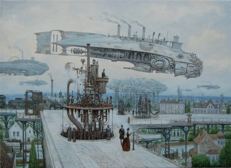 |
| NOT practical, but still fantastic! North Wind by *Voitv |
There are still some interesting things to describe in the Engine room and some proposals for how this airship would actually be operated. I know I've promised that I will be dealing with the crew's comforts as well. So to make things a little clearer I'm going to split these posts into two streams. One will continue with the technical aspects of the design and operation of our ship and the other will deal with the more "colorful" and human friendly aspects. That way I can continue to indulge in which ever side I feel like, without disrupting the overall flow of the series.
This post will be the next in the "Technical Stream", the first "Crew Stream" post will be up when I get around to writing it.

First a quick recap of the Airship which we are discussing, If you would like to start at the beginning of this series go here: Practical Airship Design Part 1
- Our Airship is a novel design utilizing low pressure steam as the lifting gas (see http://www.flyingkettle.com/jbfa.htm) Because steam has only 60% of the lift of helium our airship is a truly immense structure, of the same general size as the Hindenburg!
- The steam is generated using a fantastically powerful heat source known simply as the "Core", the exact nature of which is "unknown", but that I have chosen to describe as being like a small fission nuclear reactor. The core is located inside a large tank of water which serves both to cool the core by generating steam and as shielding for the crew.
- Propulsion is by large counter rotating props on the stern of the airship abaft the fins. These props are driven by an electrical engine that derives its power via Tesla wireless transmission from turbine driven generators in the engine room amidships.
- The turbine is driven by high temperature and high pressure steam produced in a flash boiler that utilizes the intense heat from inside the core.
- The hull of our airship is pretty conventional looking, being similar to the large rigid airships developed by Zeppelin. She is a fabric covered duraluminum truss structure like the Graf Zeppelin, or the Hindenburg. A shell like structure covers the top portion of the hull, called the condenser, and a pair of elegant funnels are placed just forward of condenser.
- The purpose of the condenser is to recover all the steam used in the turbine, and any steam vented from the lift system, by condensing it back to water to be re-used in the Steam Generator. The condenser is sized to take ALL the steam generated when the core is operating as it must be continuously cooled. In the event of an emergency, a condenser failure from damage, or if there is too much back pressure through the condenser, steam can be directed to the funnels and exhausted to atmosphere. Of course this is wasteful of the water and automatically limits the duration of any flight, so this would only be used if absolutely necessary.
- As is typical of the big rigid airships, heavier loads are placed along the bottom of the hull either inside it along the keel or in extensions that extend beneath.
- From forward we have the crew accommodations (officers and passengers) and the flight deck, from which the airship is controlled. Proceeding aft of this is the forward cargo hold (and armory when on military service), above this is the remaining crew accommodations, next aft is the engine room, the reactor/steam generator with its large water tank, the aft cargo hold, and finally an emergency steering and control position inside the lower fin.
- These spaces are connected by a narrow triangular "keel walk" similar to that found in the Hindenburg.
If you recall from Part 5, the after end of the engine room is made up of the flash, high pressure, steam boiler. This boiler is integral with the water tank that surrounds the core. On either side against the walls of the engine room are the primary and secondary feed pumps used to insure a steady flow of water into the flash boiler. The primary pump is electrically driven whereas the secondary is a conventional steam driven feed pump. Forward of this is the primary steam turbine and its directly connected Tesla generator set. Along the walls of the engine room are work benches, tool and spare part lockers, and the panels containing all the gauges and controls necessary to monitor the boiler, turbine and generator.
The generator looks pretty conventional where it is connected to the turbine, but it gets very interesting and weird looking above. The power is transferred to the main engine at the stern by wireless transmission using the "Tuned Resonance" system that Tesla invented (I'm assuming that we have perfected it) This requires that the very high voltages and currents be sent up an antenna like structure reaching from the engine room all the way to the center of the hull. I imagine this structure to look a lot like some of the fantastic equipment you see in a Frankenstein movie.
Forward of the generator is the control area for the engine room. The "Watch Engineer" is stationed here to monitor the activity in the engine room. There is a desk and file cabinet on the right side, which is my "Chief Engineer's Office", and on the left side there is a partitioned off space with a table and chairs for the watch to sit when taking a break. Against the forward wall of the engine room is the stairway leading up to the keel walk.
Traditional rigid airships had all their controls consolidated in the control car near the bow. This is true of our airship as well with one major exception. Traditional airships used the balance between inflation and ballast to control the static lift condition of the ship. These were simple open valve and close valve controls. In our ship however, the control of static lift is more complex. The engineers must maintain a careful balance of steam volume, temperature and condensation rate. So I have decided to concentrate that control in the engine room itself. Since we have a single engine whose power comes from inside the engine room as well, it makes sense to concentrate all the engineering personnel there. This is more like the situation in a surface ship, where the bridge could steer, but all other functions were controlled from the engine room on orders sent from the bridge by either engine "telegraph" or voice pipe.
Of course "flying" an airship is more than simply controlling the engine speed, and ship's buoyancy, so there are traditional controls on the flight deck, which I will discuss in a later post about the layout of the flight deck itself.
In flight there are three kinds of orders that could be sent to the engine room.
Engine speed; 1/4, 1/2, 3/4, Full, Flank (or Emergency), and direction forward or astern.
Static Lift; positive (light), neutral, or negative (heavy).
Hull trim; pitch up or pitch down.
These are sent by means of three "telegraphs" similar to those used on surface ships for engine control. These telegraphs are located in the control area of the engine room so that the Watch Engineer can keep an eye on them and relay the required orders to the rest of the engine room watch. There is also a "Telephone" connection direct to the flight deck. This might be a an old fashioned speaking tube rather than an electrical telephone, I haven't decide which yet.
I'll be trying to illustrate the commands and orders that would be given when this ship is underway in a later post.
While this seems like a fairly large space as described, it should be kept in mind that the space is very narrow maybe at most 5 meters across and most of the floor space is taken up by the turbine and all its ancillary equipment. It would also be HOT, not unlike the stoke hold and engine room in a narrow hulled destroyer or torpedo boat. I suspect that, apart from the lack of coal to shovel, an engine room hand would not see much difference between being afloat and being aloft in a vessel like this one. In our Role Play we actually call the engine room crew the "Black Gang" and the lower ranks are called "Stokers" just like in the Victorian surface navy.
Thanks for reading and join me next time for more "Practical Airship Design".
Keep you sightglass full, your firebox trimmed and your water iced.
KJ
You can follow the full design thread by clicking on the tag "Flight Engineer".


~ 0 comments: ~
~ Post a Comment ~